ESP32-C6-Zero (Waveshare)
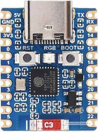
- Chip „ESP32-C6FH4“
- RISC-V 32-bit single-core processor
- up to 160 MHz
- 320KB ROM
- 512KB HP SRAM and 16KB LP SRAM
- 4MB Flash
- Support multiple low-power modes
- WiFi 6
- Bluetooth 5 and IEEE 802.15.4 (Zigbee 3.0 and Thread)
- Operating voltage: 2,2 - 3,6 V
- Board:
- Type-C USB-Connector
- Spannungsregler (LDO):
- Typ: Microne ME6217C33M5G
- Ausgangsleistung: max. 800 mA
- Dropout-Spannung: 0,1 V
- Ausgangsspannung: 3,3 V
- Eingangsspannung: min. 4,3V (Vout + 1 V), max. 7 V
- Eigenverbrauch: 100 µA
- Stromverbrauch:
- Im „Deep-sleep“ mode 8-15 µA
- Im „Light-sleep“ mode ~2,5 mA (CPU is in a low-power state, but RAM and peripherals can be accessed)
- Im „Active mode“ ohne Wi-Fi ~ 33 mA
Entwicklungsumgebungen:
- espressif ESP-IDF
- Arduino IDE
Links
Pin-Belegung
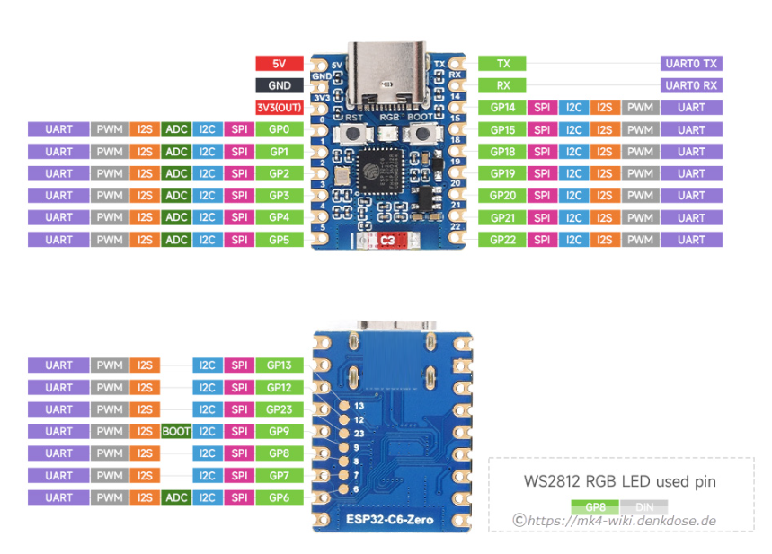
- On-Board RGB-LED (WS2812B) ⇒ GPIO8
 Die LED erwartet die LED-Farben Bytes in der Reihenfolge: R, G, B
- BOOT-Button ⇒ GPIO9 (active low)
Verwendbare IO-Ports
| Port | Pin | Verwendbar | Hinweise |
|---|
GPIO0/1/2/21 and the I2C bus on GPIO22/23
Strapping Pins
MTMS (GPIO4), MTDI (GPIO5), GPIO8, GPIO9, and GPIO15
Boot-Mode
GPIO 8 and GPIO 9 are Strapping Pins, used during the chip's power-on/reset sequence to determine the boot mode.
GPIO 9: Controls whether the chip boots from internal Flash (Default: High) or enters Serial Download Mode (Low). On your Glyph board, this pin is connected to the onboard BOOT button.
GPIO 8: Determines the boot behavior and log output. It should ideally be pulled High or left floating during reset for normal operation. Avoid connecting peripherals to these pins that might pull them to an unexpected state during startup.
USB
GPIO12 and GPIO13 are for USB
JTAG
- GPIO4 (mTMS) - Strapping
- GPIO5 (mTDI) - Strapping
- GPIO6
- GPIO7
Schaltplan
Modifikationen
Zur Verbesserung der Sende/Empfangsleistung kann man die Chip-Antenne durch einen einfachen, 31 mm (Lambda/4) langen Draht ersetzen. Dieser wird an der Stelle verlötet wo die weisse Markierung für die Chip-Antenne auf der Pnatine beschriftet ist:


Das ergibt aus eigenen Messungen eine Verbessung um 10-12 dBm!
Programmierung mit Visual Studio Code und ESP-IDF
Board-Konfiguration ⇒ keine
Programmierung mit "Arduino IDE"
- Arduino IDE herunterladen und installieren
ESPHome Integration
esphome:
  name: my-esp32-c6-board
  friendly_name: esp32-c6-test

esp32:
  board: esp32-c6-devkitc-1
  framework:
    type: esp-idf