Reverse-Engineering Firmware "BG9T-14C095-AK"
THIS PAGE IS „WORK IN PROGRESS“
CAN-Bus Communication
- UDS CAN-Port: HS-CAN
- UDS CAN-ID: 0x726
Memory Map
- SFR1:
0x0000_0000 .. 0x0000_03FF - RAM:
0x0000_0400 .. 0x0000_C3FF - SFR2:
0x0004_0000 .. 0x0004_FFFF - Data (CCC):
0x0006_0000 .. 0x0006_1FFF - E2 Data (EEPROM):
0x0006_2000 .. 0x0006_2FFF - Firmware address:
0xFFF4_0000 .. 0xFFFF_FFFF
R32C Ports used
UART3(symbolu3…) ⇒ Connected to RFRX-Receiver as „LIN0“, but in fact it's not LIN but an simple UART protocol used over LIN transceiver (20)- TLE7259 Pin 1 (RxD) → R32C Pin 73, P4_3 / TXD3 / IIO1_3
- TLE7259 Pin 4 (TxD) → R32C Pin 75, P4_2 / RXD3 / IIO1_2
- TLE7259 Pin 6 (BUS) → R32C Pin 8, P14_6 / /INT8
???⇒ Connected via SBC/Transceiver (4) to MS-CAN BusCAN1/CAN2⇒ Connected via transceiver (15) to HS-CAN Bus- R32C Pin 1, P9_6, CAN1OUT/CAN2OUT
- R32C Pin 2, P9_5, CAN1IN,CAN1WU / CAN2IN, AN2WU
CAN1
0x00007D
9B
C5
D2
E3
E5
F2
0x047800-0x047BFF

CAN2
C7
C9
D4
E7
F4
0x047400-0x0477FF
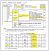
UART3
UART3
-----------
40098	IFS0	Input Function Select Register 0 (bit2+3 select pins for UART3 CLK, RXD and CTS) User Manual p. 548

000dd		S3TIC	Transmit Interrupt Control Register
000fd       S3RIC	Receive Interrupt Control Register
001e0		U3MR	Transmit/Receive Mode Register
001e1		U3BRG	Bit Rate Register
001e2-001e3	U3TB	Transmit Buffer Register
001e4		U3C0	Transmit/Receive Control Register 0
001e5		U3C1	Transmit/Receive Control Register 1
001e6-001e7	U3RB	Receive Buffer Register
001f0		U34CON	Transmit/Receive Control Register 2


0x1E5 => UART3 Transmit/Receive Control Register 1
RI (Bit 3) Receive Complete Flag (1= Data held in U3RB Register)
TI (Bit 1) Transmit butter empty

0x1E6..1E7
TPMS Functions
C2-36 TPMS LR SIGNAL
C2-35 TPMS LR GND
C2-19 TPMS RR SIGNAL
C2-20 TPMS RR GND

C1-19 TPMS RIGHT FRONT SIGNAL
C1-20 TPMS RIGHT FRONT GND

C1-36 TPMS LEFT FRONT SIGNAL
C1-35 TPMS LEFT FRONT GND

ATSP6
ATSH726
STCSEGT1

1: 2F 2A 25 03 FF 00 00 00 FF 00 00 00
2: 2F 2A 25 03 00 FF 00 00 00 FF 00 00
3: 2F 2A 25 03 00 00 FF 00 00 00 FF 00
4: 2F 2A 25 03 00 00 00 FF 00 00 00 FF

Ohne Session:
> 7F 2F 7F

Aufbau einer Extended Diagnostic Session (0x03)
10 03
> 50 03 00 32 01 F4

Mit Session:
7F 2F 31

0x31 - requestOutOfRange - This NRC indicates that the requested action will not be taken because the server has detected that the request message contains a parameter which attempts to substitute a value beyond its range of authority (e.g. attempting to substitute a data byte of 111 when the data is only defined to 100), or which attempts to access a DataIdentifier/RoutineIdentifer that is not supported or not supported in active session.

    0x2F // UDS - Input Output Control
    0x2A // Identifier 0x2A25 High, 0x2A = 00101010, Bit 7 = ‚0‘ = FALSE: the ECU shall send a response, that is, no suppression of a positive response shall be done
    0x25 // Identifier 0x2A25 Low
    0x03 // Start (0x00, 0x02 and 0x03 are valid values)
    0xFF // State Initiator 1
    0x00 // State Initiator 2
    0x00 // State Initiator 3
    0x00 // State Initiator 4
    0x01 // Select Initiator 1
    0x00 // Select Initiator 2
    0x00 // Select Initiator 3
    0x00 // Select Initiator 4

Das Ganze muss mit Diagnostic Session ID 0x03 erfolgen.
Von den "Select Initiator" Bytes muss genau eines auf 0x01 stehen, damit wird der Initiator ausgewählt.
Mit den "State Initiator" Bytes wird festgelegt ob der Initiator an oder aus ist (es muss das entsprechende Byte auf 0xFF oder 0x00 stehen wobei vermutlich nur eines der Bits ausgewertet wird).
HS-CAN Bus
BCM has HS-CAN of car connected through/from pins 6 + 7 of (C3), via CAN-Transceiver TJA1042 (15) to Port P9 pins P9_6 + P9_5 of CPU (1). The firmware initializes these pins to be connected to CAN2 controller. The init is done at the subroutine 0xFFFA_1EDE.
Section (1): Setup P9 pins for CAN2
CODE:FFFA1EDE hscan_init1:                            ; CODE XREF: sub_FFFB04D4-E466↓p
CODE:FFFA1EDE                 PUSHM   A1
CODE:FFFA1EE0                 BSET    prc2, prcr      ; Recommendation of manual, set PRC2 to 1 just before changing direction register
CODE:FFFA1EE5                 BSET    pd9_6, pd9      ; Set port P9, pin 6 as output (connected to TXD of ext. CAN transceiver)
CODE:FFFA1EE9                 BSET    prc2, prcr      ; Recommendation of manual, set PRC2 to 1 just before changing direction register
CODE:FFFA1EEE                 MOV.B   #101b, p9_6s    ; Set function of port P9, pin 6 as CAN2OUT (connected to CAN2 controller)
CODE:FFFA1EF3                 BSET    prc2, prcr      ; Recommendation of manual, set PRC2 to 1 just before changing direction register
CODE:FFFA1EF8                 BCLR    pd9_5, pd9      ; Set port P9, pin 5 as input (connected to RXD of ext. CAN transceiver)
CODE:FFFA1EFC                 BSET    #4, ifs1        ; Set CAN2 input to be connected to port P9, pin 5 (P9_5)
CODE:FFFA1F01                 BSET    prc30, prcr3    ; Recommendation of manual, set PRC30 before changing port 3
CODE:FFFA1F06                 MOV.B   #0, p9_6s       ; Set function port P9, pin 6 as GPIO
CODE:FFFA1F0B                 BSET    pd3_7, pd3      ; Set pin 7 of port P3 as output
CODE:FFFA1F0F                 BCLR    p3_7, p3        ; Set pin P3_7 to level "0"
CODE:FFFA1F13                 BCLR    prc30, prcr3    ; Recommendation of manual, set PRC30 before changing port 3
CODE:FFFA1F18                 BTST    #2, c2str       ; if CAN2 is in sleep mode (SLPST=1) goto loc_FFFA1F2B
CODE:FFFA1F1D                 JEQ/Z   loc_FFFA1F2B    ;


